Gas Springs - Stainless Steel - Thread at Both Ends
Stainless steel (AISI 304) gas springs with thread
We’ll usually dispatch your order the same day with expected delivery within 2-4 days. This applies to all stocked gas springs
See quantity discounts and prices by clicking on the shopping cart next to the required product.
Use the range sliders below for quick and easy navigation.
The threaded gas springs can be combined with our large range of end fittings and fittings. We have a very wide selection of end fittings in stock in plastic, galvanised iron, stainless steel and acid-proof stainless steel. See the range here.
88-70023-description
Stainless steel 304
88-70024-description
Stainless steel 316
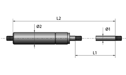
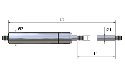
- GFRF-6-20-50In stock: 179Material Stainless steel 316Ø1 - Piston Rod diameter (in) 0.2362Ø2 - Tube diameter (in) 0.5906L1 - Stroke (in) 0.7874F - Force (lbs) 11.2404L2 - Unloaded length between thread (in) 3.3858K - Force ratio 1.3000G - Thread (in) 0.2362
- GFRF-6-20-75In stock: 179Material Stainless steel 316Ø1 - Piston Rod diameter (in) 0.2362Ø2 - Tube diameter (in) 0.5906L1 - Stroke (in) 0.7874F - Force (lbs) 16.8607L2 - Unloaded length between thread (in) 3.3858K - Force ratio 1.3000G - Thread (in) 0.2362
- GFRF-6-20-100In stock: 186Material Stainless steel 316Ø1 - Piston Rod diameter (in) 0.2362Ø2 - Tube diameter (in) 0.5906L1 - Stroke (in) 0.7874F - Force (lbs) 22.4809L2 - Unloaded length between thread (in) 3.3858K - Force ratio 1.3000G - Thread (in) 0.2362
- GFRF-6-20-100-TIn stock: 60Material Stainless steel 304Ø1 - Piston Rod diameter (in) 0.2362Ø2 - Tube diameter (in) 0.5906L1 - Stroke (in) 0.7874F - Force (lbs) 22.4809L2 - Unloaded length between thread (in) 3.3858K - Force ratio 1.3000G - Thread (in) 0.2362
- GFRF-6-20-125In stock: 179Material Stainless steel 316Ø1 - Piston Rod diameter (in) 0.2362Ø2 - Tube diameter (in) 0.5906L1 - Stroke (in) 0.7874F - Force (lbs) 28.1011L2 - Unloaded length between thread (in) 3.3858K - Force ratio 1.3000G - Thread (in) 0.2362
- GFRF-6-20-150In stock: 179Material Stainless steel 316Ø1 - Piston Rod diameter (in) 0.2362Ø2 - Tube diameter (in) 0.5906L1 - Stroke (in) 0.7874F - Force (lbs) 33.7213L2 - Unloaded length between thread (in) 3.3858K - Force ratio 1.3000G - Thread (in) 0.2362
- GFRF-6-20-150-TIn stock: 60Material Stainless steel 304Ø1 - Piston Rod diameter (in) 0.2362Ø2 - Tube diameter (in) 0.5906L1 - Stroke (in) 0.7874F - Force (lbs) 33.7213L2 - Unloaded length between thread (in) 3.3858K - Force ratio 1.3000G - Thread (in) 0.2362
- GFRF-6-20-175In stock: 179Material Stainless steel 316Ø1 - Piston Rod diameter (in) 0.2362Ø2 - Tube diameter (in) 0.5906L1 - Stroke (in) 0.7874F - Force (lbs) 39.3416L2 - Unloaded length between thread (in) 3.3858K - Force ratio 1.3000G - Thread (in) 0.2362
- GFRF-6-20-200In stock: 179Material Stainless steel 316Ø1 - Piston Rod diameter (in) 0.2362Ø2 - Tube diameter (in) 0.5906L1 - Stroke (in) 0.7874F - Force (lbs) 44.9618L2 - Unloaded length between thread (in) 3.3858K - Force ratio 1.3000G - Thread (in) 0.2362
- GFRF-6-20-200-TIn stock: 61Material Stainless steel 304Ø1 - Piston Rod diameter (in) 0.2362Ø2 - Tube diameter (in) 0.5906L1 - Stroke (in) 0.7874F - Force (lbs) 44.9618L2 - Unloaded length between thread (in) 3.3858K - Force ratio 1.3000G - Thread (in) 0.2362
Cylinder and piston rod: Stainless steel 304 / Stainless steel 316
Oil: The oil is a common lubrication oil, but is not approved for food use.
We have stainless steel gas springs (AISI 316) with food-grade oil in stock. See the range here.
Gas: Nitrogen N2 Std.
Atmospheric air contains 78.09% nitrogen and is the basis for the production of nitrogen by means of distillation of liquid air.
Nitrogen is odourless, colourless, non-toxic, and non-flammable.
If the gas springs are to be used in humid environments, stainless gas springs are recommended. In harsh environments such as the maritime or in food production, gas springs made of stainless steel 316 are used. Our gas springs in stainless 316 are filled with food grade oil (Omnilube FGH 1046). The gas springs are FDA approved. See the range here.
Unloaded length mideye to mideye: +/- 0.01181 "
Piston Rod: +/- 0.0788 "
Force: +/- 10 %
If you want a PDF datasheet or a 3D CAD drawing of the spring in .step, .iges or .sat format, these can be downloaded for free by clicking on the 3D CAD symbol next to the item number in the table.

The force quotient is a calculated value that indicates the force increase/loss between 2 measurement points.
The force in a compression gas spring increases the more it is compressed, in other words as the piston rod is pushed into the cylinder. This is because the gas in the cylinder is compressed more and more due to displacement changes inside the cylinder, thereby increasing the pressure that results in the axial force that pushes the piston rod.

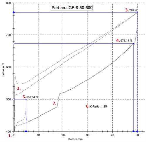
- Force at unloaded length. When the spring is unloaded, it provides no force.
- Force at initiation. Due to a combination of frictional force added to X number of N produced by the pressure in the cylinder, the curve clearly shows that the force rises pretty much as soon as a gas spring is compressed. Once the friction has been overcome the curve falls. If the spring has been at rest for some time, it may again require extra force to activate the gas spring. The example below shows the difference between the first and the second times the gas spring is compressed. If the gas spring is used regularly, the force curve will be close to the bottom curve. A gas spring that is at rest for some time will be more likely to be closer to the top curve.
- Maximum force on compression. This force cannot really be used in structural contexts. The force is achieved only as a snapshot when the continuous pressure/travel stops. As soon as a gas spring is no longer travelling, the gas spring will attempt to return to its start position and therefore the usable force is less and the curve falls to point 4.
- Maximum force yielded by a spring. This force is measured at the start of the gas spring’s recoil. This shows the correct image of how much maximum force a gas spring yields when it is stationary at this point.
- Force provided by the gas spring in tables. By normal standards, the strength of the gas spring is provided from a measurement of the force at the remaining 5 mm travel towards its extended status, and at still status.
- Force quotient. The force quotient is a calculated value that indicates the force increase/loss between values at point 5 and point 4. Thus a factor for how much force a gas spring loses on return from its maximum travel point 4, to point 5 (max. travel extended – 5 mm). The force quotient is calculated by dividing the force at point 4 by the value at point 5. This factor is also used in the reverse situation. If you have the force quotient (see value in our tables) and the force at point 5 (the force in our tables), the force at point 4 can be calculated by multiplying the force quotient by the force at point 5.
The force quotient is dependent on the volume in the cylinder combined with the thickness of the piston rod and the quantity of oil. This varies from size to size. Metals and fluids cannot be compressed, and it is therefore only the gas that can be compressed inside the cylinder. - Damping. Between point 4 and point 5 a bend can be seen in the force curve. It is at this point that the damping starts, and there is damping for the remaining part of the travel. Damping occurs through oil needing to seep through holes in the piston. By changing the combination of hole sizes, the quantity of oil, and oil viscosity, the damping can be changed. Damping can/should not be removed entirely, as a fully compressed gas spring on sudden free movement of the piston will not be damped, and thereby the piston rod can be extended from the cylinder.
Gas springs contain nitrogen gas under high pressure. This is a type of gas that cannot burn or explode, nor is it toxic if inhaled. No attempt must be made, in any circumstances, to take the gas spring apart or to refill it - this is extremely risky due to the high pressure! Do not burn, puncture, squash or dent the gas spring, and do not weld the surface of the cylinder. Do not scratch, paint or bend the piston.
Never use gas springs as a safety device. If damage to a gas spring could result in personal injury, provision must be made for this by means of a safety device. If any construction incorporating a gas spring could cause personal injury in the event of loss of gas from the spring, an additional safety device must be used to prevent injury. In some constructions, locking tubes for gas springs can be used. This safeguards the construction in the event of a sudden pressure drop in the gas spring. Read more
Gas springs must be stored and fitted with the piston pointing downwards and at 45 degrees to the horizontal. This is important, as this fitting will ensure that internal glands will remain lubricated by the oil inside the gas spring.
If a gas spring is fitted horizontally or with the piston rod facing upwards, the oil will run out of the gasket, which will cause it to dry out. This will eventually impair the function and ultimately the gasket may leak, causing the gas spring to lose its force.
For each fitting you must ensure that there is no sideways deflection or other forces that will affect the gas spring in any way other than free axial movement in the gas spring’s longitudinal direction.
When a gas spring has not moved for a while, it may well take a little extra effort to get it moving again. That is perfectly normal.
Note also that normally you cannot simply compress a spring of more than 200N with your hands.
It is recommended that in constructions with gas springs a physical stop is used to ensure that the gas spring is not overloaded. A physical stop avoids the piston rod being pressed right down. In other words, a section of the piston rod must always be visible. This safeguards the characteristics of the gas spring and ensures an optimal service life.
If the door is physically large and/or heavy, we recommend that you use 2 gas springs in the construction. Otherwise there is a risk of distortion in the construction. This can limit the functionality of the gas spring and shorten the service life greatly. In unfortunate situations, it may even ruin the construction.
If the construction already has two gas springs installed, it is always recommended to replace both gas springs at the same time. There may be variation in the force of an old and a new gas spring and this variation may result in unwanted functionality and a shorter service life.
Avoid lubricating the piston rod, as the range of gas springs is maintenance-free. It is possible to protect the gas spring with rubber bellows if the gas spring is to be used in an unclean environment.
Gas springs are filled at 68°F, and the initial force is therefore measured at 68°F.
The force will change by approximately 3-3.5% per 50°F. The colder it is, the weaker the gas spring becomes.
Our gas springs work best in temperatures between -22°F and +176°F. Using the springs in temperatures close to those limits will produce an altered force, and maximal usage cannot be recommended.
Gas springs are designed to perform no more than 5 strokes per minute at 68°F. If this is exceeded, there will be a build-up of heat inside the gas spring that may result in leaky glands.
Gas springs will lose pressure slightly over time, compared with the original pressure at the time they were fitted. A pressure loss of up to 10% may be expected.
Always use the shortest possible travel, and choose the largest possible diameter on the cylinder - this increases the durability. Long and thin gas springs will be weaker than short and wide gas springs.
Internet Explorer Incompatibility
This website unfortunately does not work well with Internet Explorer. We recommend using one of the following free browsers:


